SEARCH SITE
CPC software features
This section highlights some of CPC's capabilities and features. If you would like to see a more comprehensive explanation of these features, please search "CPC Manual" in our Support page's knowledge engine:
NEW - Web & Cloud-Based Control
CPC 2020 now has optional features that include a web-based browser, with SSL protection, for control and viewing of your Econoclave or oven systems on any authorized mobile or desktop device while on your LAN (Local Area Network). In addition, we also offer a cloud-based version for remote equipment monitoring, control, and data analysis. With either of these secure composite processing controls platforms, you will have advanced accessibility with dedicated user levels for controlled user access for viewing and daily operations of your Econoclave or oven systems.
Here are some more key features you will be able to safely and securely access on your mobile or desktop devices:
- Responsive cloud-based monitoring and data analysis.
- Run reports and view them in a web-based browser.
- Start and stop your Econoclave or oven systems.
- Write or modify cures, create parts, and more.
Please contact us to discuss the many options available.
Viewing Screens
Main screen display
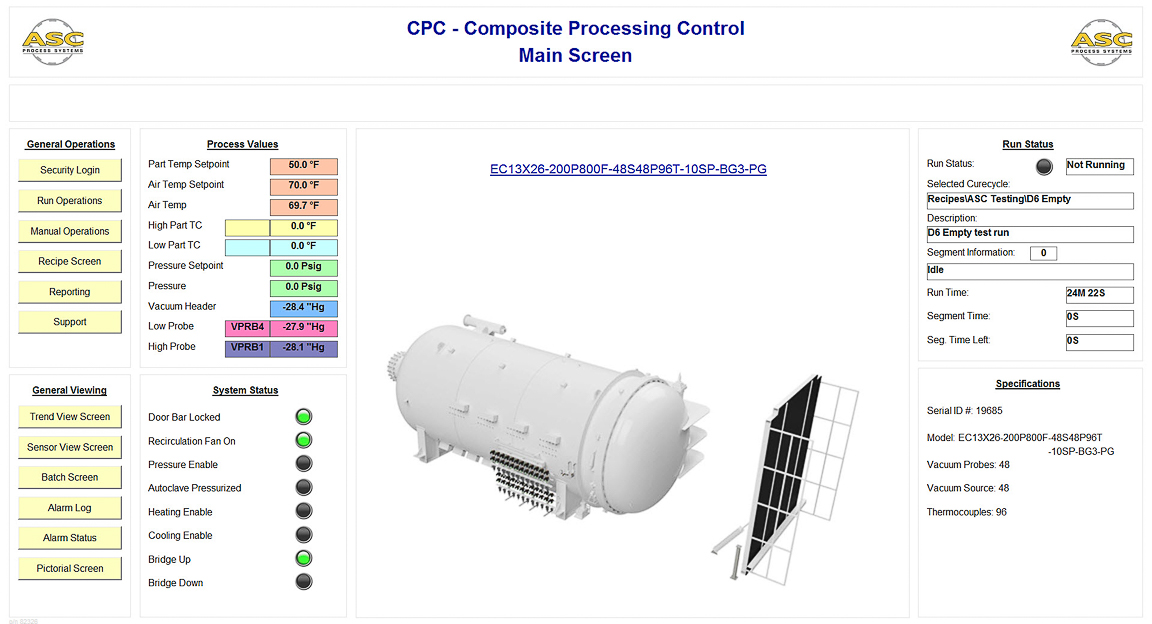
CPC's Main Screen is custom designed to the customer's needs. It typically includes process values such as Pressure, Air Temp, Vacuums, Hi, and Low Part TCs. It also includes run information such as Run Status, Elapsed Time, Recipe name, and Segment information. An equipment photo is typically displayed on the main screen.
Sensor viewing screen
The sensor viewing screen shows all process variables, including all part thermocouples, all vacuum probe readings, and AirTC, Pressure, System Vacuum, and any other relevant process value. Each part thermocouple and vacuum probe is displayed along with it's enable status and what part it's attached to.
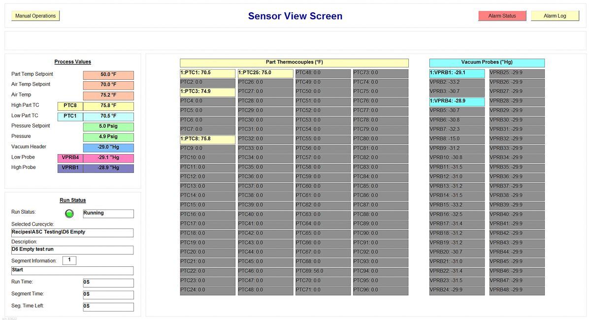
This screen also provides the ability to enable or disable sensors during a cure cycle. The operator merely has to double-click the sensor in the list and a QuickView window will be displayed.
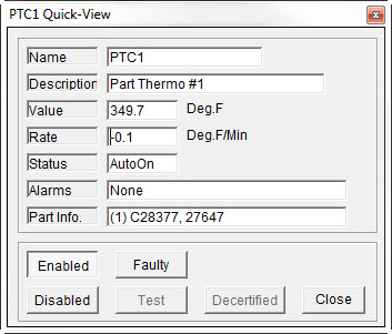
Click the image to see the QuickView form
Trend viewing screen
The trend screen displays process values in trend form. The trend display plots each value in a different color, line-type (solid, dash, dot), and line width. The operator can easily configure a selected set of sensors to view, and can then store that configuration set or group to the system. This allows immediate recall of the specific set of sensors for viewing.
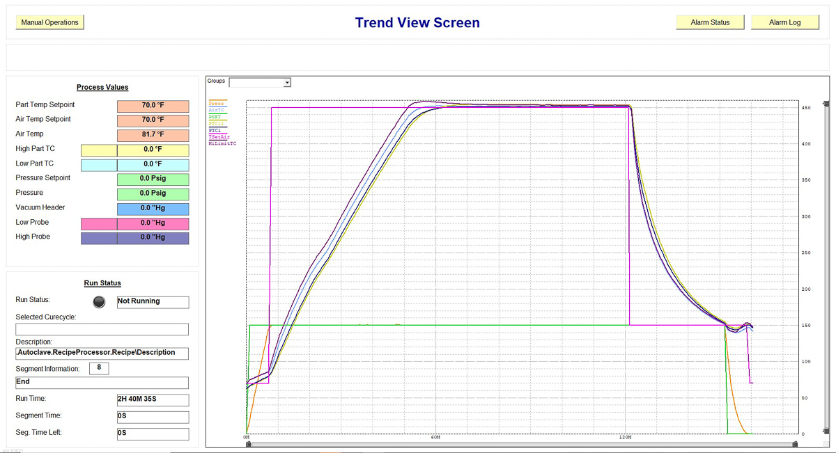
The trend screen also includes a drop-down selection that lets the operator select a specific part. When a part is selected, the system will display only the sensors on that part (Part thermocouple and vacuum probes) as well as main process values (ie. Air Temp, Pressure, etc.)
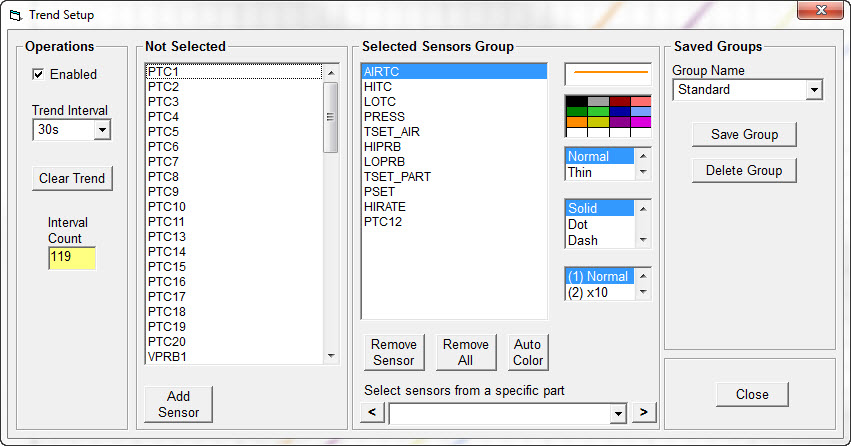
Click the image to see the Trend Setup form
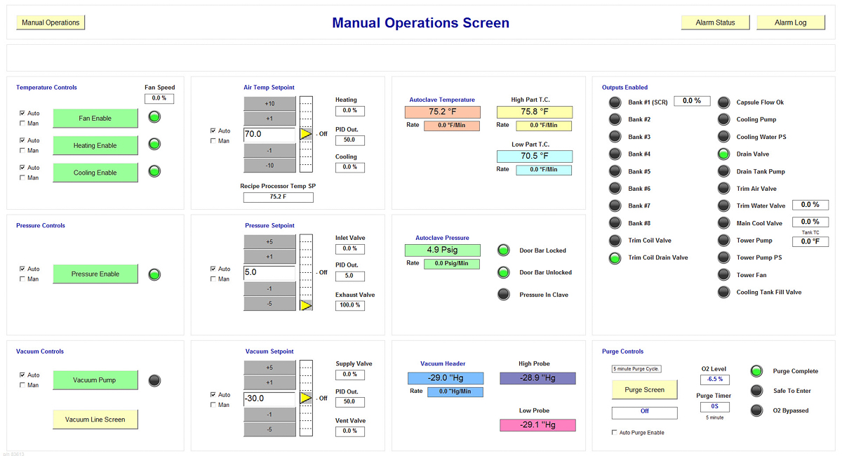
Manual operations screen
The manual screen provides control of key systems and components on the equipment. Each mode can be switched between Auto and Manual. Button, lights, and setpoint controllers are provided for easy manipulation of the system. When the operator places a mode in the manual, the system will record the action to the alarm messages. The screen also can be custom configured with process values and trend displays.
Batch View Screen
The batch view screen shows a listing of all parts in the run as well as a display of the current process and the trend. The batch listing displays the part #, serial # (configurable), highest and lowest TC and vacuum probe on the part, and also the current soak time for each part.
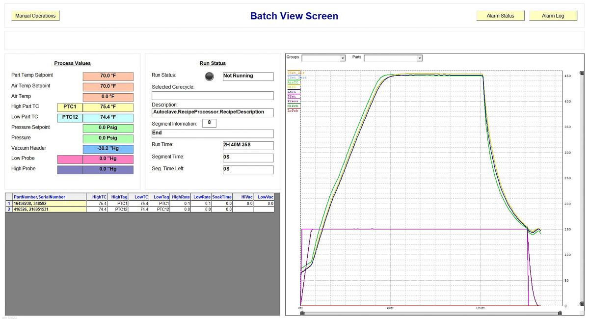
Another nice feature is that when the operator clicks a specific part row, the Trend Display will automatically reconfigure itself to show AirTC, Pressure, and each part thermocouple and vacuum probe on that part.
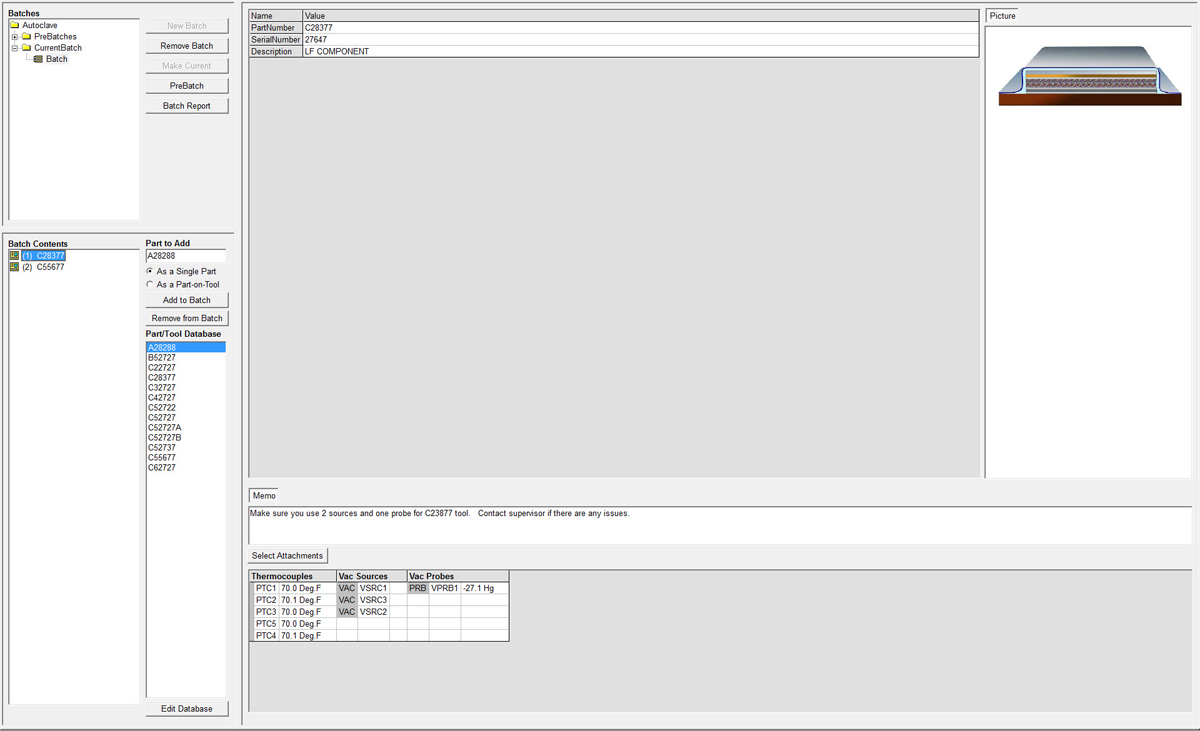
Batch/Part Entry Screen
The batch/part entry screen is used by the operator to enter part information prior to a run. Once a part is entered, the screen provides an attachment form to select part thermocouples, vacuum sources, and vacuum probes for the part. An integral part database can be used to speed the entry process.
See the "Part Entry" section on this page for specific details.
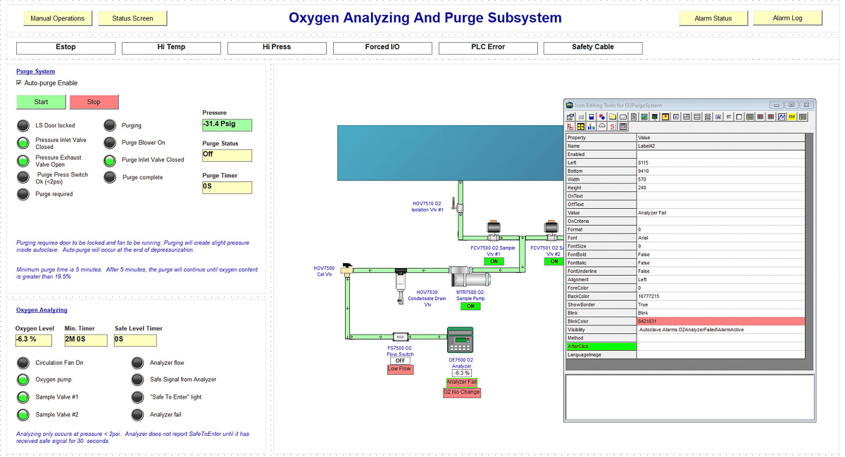
Pictorial P&I Screen
The pictorial screen shows the current equipment, including valves, sensor values, and flow indication. The screen is customized to each equipment. Often, multiple pictorial screens are provided to show all systems on the autoclave.
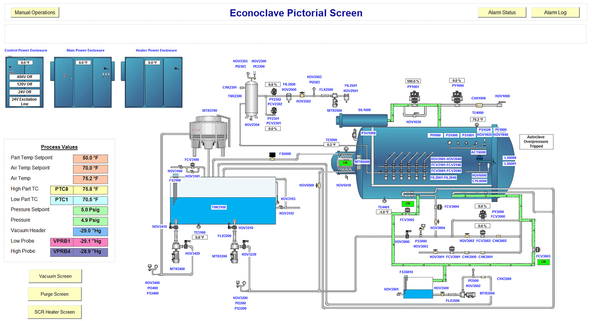
The screen is animated with flow arrows moving in piping and the autoclave. There are also displays of valve positions with color changes and % indicators.
Run operations screen
The Run Operations screen provides a step by step procedure for how to set up and start an automatic cure cycle. The screen is fully configurable, so the procedure might vary from one customer to the other. The steps include vacuum connection to parts, part entry, integrity checks (leak test, field check, etc.), and any other step the customer might want to be programmed.
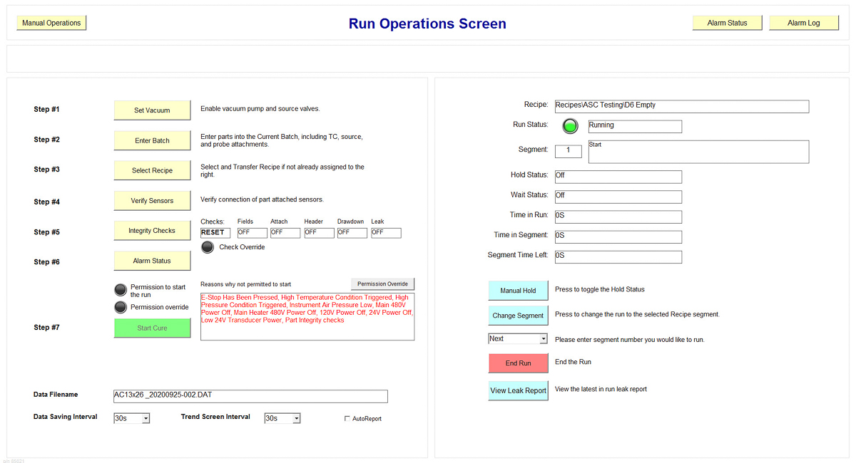
The screen also shows the current run status, elapsed time, segment information, and can have any other customer-requested information displayed.
Once the run has been started, the screen can also be used to change segments, put the run in the hold, or manual end the run. CPC also allows an operator to jump the run to a previous segment - this often used if the operator wants to jump back to a ramping segment. All run operation actions can be modified and secured for specific permitted groups.
Integrity Checks screen
The Integrity Checks screen is used to initiate final system checks for the loaded parts. The integrity checks include a field check (operator entered information), sensor check (sensors reading correctly), header check (vacuum control ok), drawdown check (part vacuum values ok), and final automatic leak test.
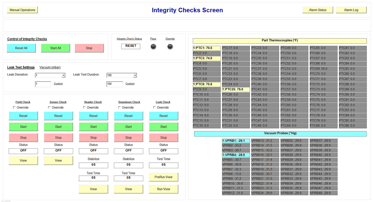
Each check is a separate process, and the system generates a unique report for each. A failed integrity check typically prevents a run from starting, however, there is an override that can be implemented to allow a run with failed checks. This is configured to meet customer requirements.
See the "Integrity Checks" section on this page for more information.
Recipe Screen
The Recipe Screen is used to program recipes for the cure cycles. The recipe screen includes a tree-view listing of recipes and recipe folders. When the recipe is clicked, the system will automatically show the contents in the spreadsheet view.
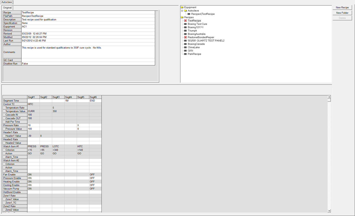
The recipe is programmed in a spreadsheet. Each row is a specific parameter or option, and each column is a distinct control segment. Segment Time and Watch groups are used to regulate when a segment changes.
Photo Maintenance Screen
CPC can also be configured with optional Photo Maintenance screens. These screens show individual items on the autoclave or oven and provide details regarding maintaining and troubleshooting each item. This requires camera access to the equipment at your facility.
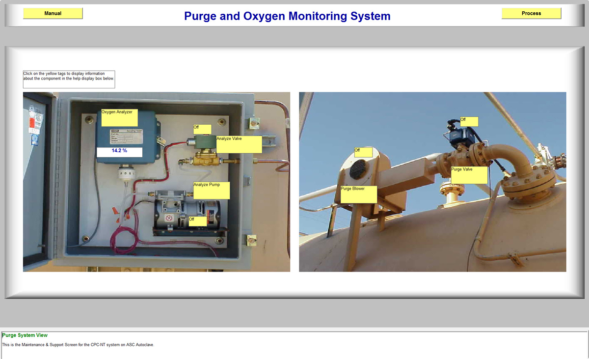
The operator clicks each yellow label section, and the information regarding the description and possible maintenance tasks show up in the help section at the bottom of the screen.
Customizing Screens
CPC has a built-in screen designer that provides ASC's controls engineers the ability to enhance and customize the screens to fit almost any application. After the system is installed, the customer can modify each screen to fit his preference. Note: Screen design is typically locked from operators.
The engineer can configure most screens using built-in graphic tools and custom scripting.
Part Entry
The part entry screen is used by the operator to enter parts and part attachments for the upcoming run.
In CPC, the parts are collectively termed a "batch". When the operator starts the part entry procedure, he will first remove the previous run's parts from the batch using the "Remove from Batch" button. Once the batch is cleared, the operator can add a part from scratch or can select a part from a pre-loaded part database. Some customers also set up CPC to input barcoded information from traveler documents.
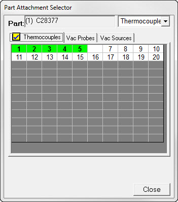
Once the part information is entered, the operator clicks the "Select Attachment" button to display the attachment form. This form shows the available thermocouples, vacuum sources, and vacuum probes. A quick click on the index number assigns those specific elements to the part. Note that the form is color-coded to indicate current status. Green means that the attachment is already assigned to the current part. Bold indicates that there is actually a thermocouple plugged into the equipment (ie. non-zero). Blank indicates that the sensor is attached to another part.
Once the attachments are assigned, the screen will show the real-time values and status of each attachment in the grid. For vacuum sources, the operator can click the action to change from VAC to OFF to VENT depending on the preference.
CPC also has a unique feature that allows multiple parts under one bag. In this scenario, the tool is first entered and then each subsequent part is entered as a "Part-on-Tool". In this way, the part inherits the tool's attachments. This is often used in production aerospace operations.
CPC is extremely flexible. You can set up the entry template to show as many fields as you want. The fields can include photos of the part/tool and detailed instructions for the operator. Also, there is no limit to the number of parts that can be run in a single cure cycle.
CPC supports pre-batching of part loads. Pre-batching allows the operator to enter parts for the next run while the current run is in process. Then, after the run completes, a single click of the "Make Current" button will transfer the pre-batch to the Current Batch. This can reduce door-open times and improve equipment effectiveness.
With CPC's integral part database, you can set up the system to automatically select the Recipe when a part is selected. This feature also includes integrity checking to make sure that all parts can be cured with the same recipe. (See Part Database section for more details.)
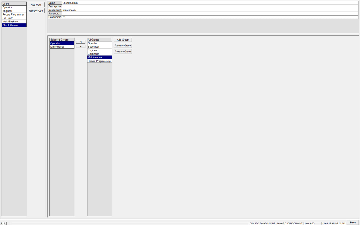
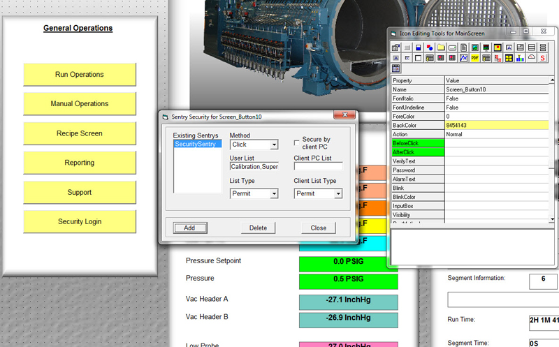
Security features
CPC has an extensive security system that allows configurable access to different screens, capabilities, and functions. The Security Screen is used to configure users and create/edit membership groups. Membership groups are specific groups that are given access to different screens or functions in the system. By assigning a group to a user, you give that user access to whatever the group allows.
Using the Objects Editor and Screen Builder, you can secure screens to a specific group or groups. You can also tweak the security provisions of recipe programming, run operations, screen building, and any other related activity.
CPC can be configured to automatically lockout the user at a predefined dormant period. You can also configure CPC to lockout at specific times of the day.
For companies running multiple CPC installations, the security system can utilize a common database. Also, each login and logout activity is stored in the database.
Equipment Control
Unlike all other competitive products, CPC takes direct control of the equipment. This means that every valve, motor, actuator, and control element is driven directly by CPC. Every input is also directly read by CPC - this includes limit switches, pressure and vacuum transmitters, and thermocouples.
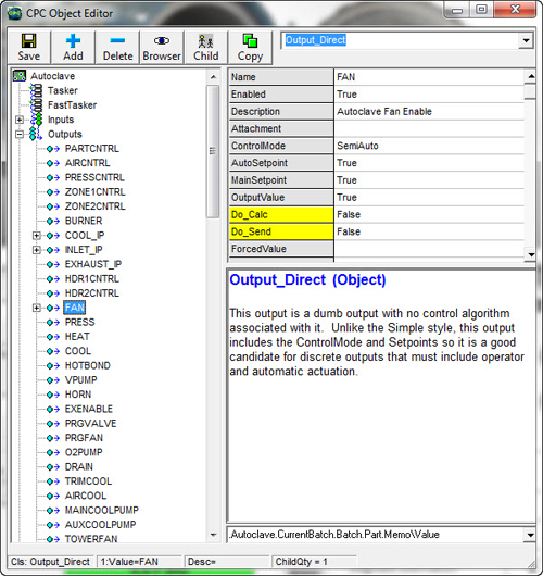
Inputs and Outputs are configured using an Object Editor. The Object Editor exposes all configurations of the system and allows the controls engineer or customer to manipulate the system, change settings, or tailor the software to meet your exact requirements.
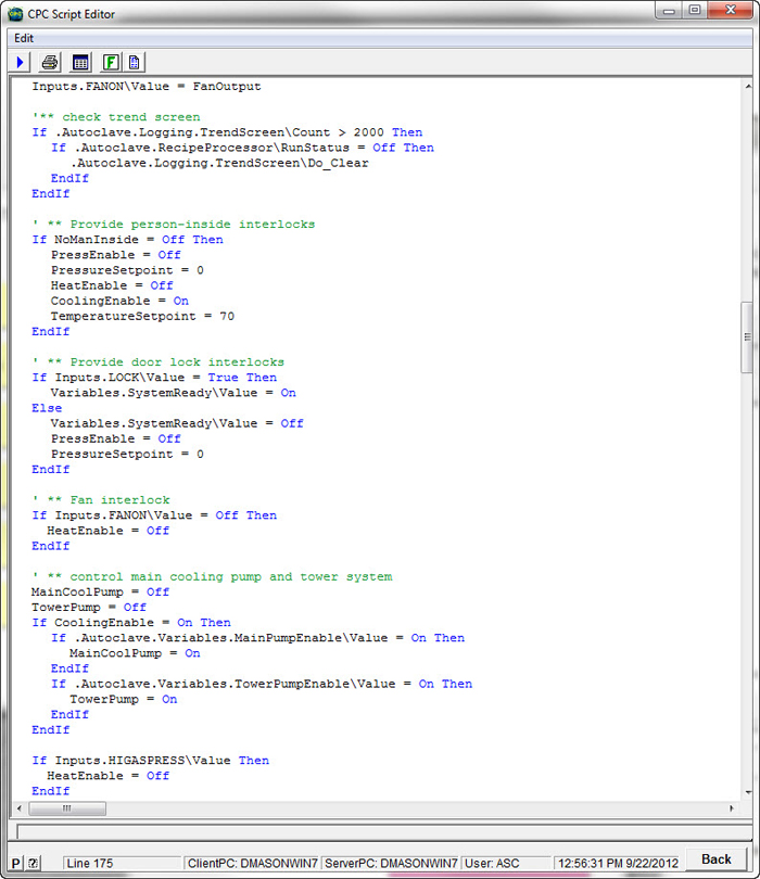
Internal logic programming is handled using CPC's advanced scripting language. This language was created by ASC and is the backbone behind CPC's machine control capability. Multi-tasked scripts are programmed and executed to provide the same type of logic control that a PLC would provide.
CPC controls multiple PID loops using a proven PID algorithm. Not only does CPC control pressure, temperature, and vacuum, but it can also be configured to control multiple hot-bonder heaters, tool heaters, and other control elements.
With a Level II Dual-PC CPC system, you get complete control and data-acquisition redundancy. While CPC systems do not require any external setpoint controllers or chart-recorders, if you prefer to have manual control backup, then this will be quoted optionally. Note that 99% of all CPC customer does not utilize manual controllers in their systems.
Recipe operations
CPC has a full-featured recipe system that provides powerful control of batch and curing processes. Recipes are programmed in the Recipe Screen.
The screen has three sections. The upper right tree-view section shows the virtual directory of recipes and recipe folders. It also shows the equipment folder and which recipe is currently selected for the run. Recipes that are disabled from operations are marked with a red X. In order to view or edit a recipe, you only have to click the recipe in the tree-view. There is no "load" operation as all recipes remain in memory during normal operations.
The upper left information shows the information related to the current recipe selected for editing. The fields include the Recipe, the virtual path, description, specification, designated equipment list, and revision information. There is also the ability to disallow the recipe from operations and associate a quality inspection card for the specific run.
What's a segment? - In CPC, a segment is a defined change in control. Any specific change that you want the system to make during an automatic run would include a unique segment. A recipe segment rarely has a fixed time associated with it and its duration is usually regulated by Watch Group triggers.
Segment Time - Segment Time is entered for segments that must have a fixed duration (ie. soak periods). Time can be entered in seconds (xS), minutes (M) or hours (H). The Segment Time parameter is also used to indicate run completion (END).
Part Temperature Control - The recipe's temperature control parameters collectively perform excellent part temperature control. The Control TC parameter is used to indicate which specific thermocouple (ie. AIRTC) or statistical reading (ie. HITC, LOTC, AVGTC) is used to drive the ramp. The Rate and Value parameter is the rate of increase/decrease (ie. deg/min) and the targeted temperature (ie. 350). The Value can also be entered as CURR to denote the "current temperature". Cascade IN, Cascade OUT and Add Per Time are collectively used to configure the air temperature thermal head (air-to-part delta) used to drive the parts during the ramp. For a document detailing this capability, please search "Part Temperature" in the Support page knowledge engine.
Pressure Control - The Pressure Rate and Pressure Value are used to ramp pressure to a predefined target. An X in the rate value indicates a "no rate" request and will result in rapid pressurization or depressurization.
Vacuum Control - CPC can control one or multiple vacuum systems. In the screenshot, you will see two vacuum headers (Header1 and Header2). Each header can be controlled at different ramp rates and to different vacuum levels.
Watch Groups - A powerful feature of CPC's recipes is the watch group. Watch groups regulate when a segment ends. You can use watch groups to "watch" a specific sensor value and then GO to the next segment when that value reaches a specific target. Multiple watch groups can be used in parallel using AND and OR actions.
Modes, Motors, and Pumps - The recipe also includes On/Off control of specific CPC control modes, equipment motors, and equipment pumps. Rows can be custom-configured to automatically actuate Heat Enable, Pressure Enable, Vacuum Enable, Fan operations, and any other item you want to control by segment.
Vacuum Line Control - The recipe contains a few parameters that regulate the position of vacuum valves during the run. Vac Line Control can be set to VAC, OFF, or VENT. The recipe also includes a function to vent or isolate a leaking part based on a specific probe reading.
Alarm Functions - CPC does not automatically set alarms during a recipe cycle and instead provides parameters in the recipe that are used to activate and deactivate alarms during the programmed cycle. Any alarm you would like to have can be easily configured in the recipe. Typical autoclave alarms include Max Air Temp, Max Pressure, Max Part Temp, Min Part Temp, Max Part Rate, Min Part Rate, Max Vacuum, Min Vacuum, Bag Break Limit, Max Air-Part Delta, Max Part Temp Delta, and many others. Every alarm also includes a Grace Period parameter that filters sporadic alarms. Note that some alarms take control limiting action while others only will sound a visual and audible alarm.
Integrity Checks
Integrity Checks are a series of software and hardware checks that occur immediately before an automatic run is started. CPC's integrity check process has been collaboratively developed with The Boeing Co over many years. The process provides the best overall check for the part and vacuum integrity in order to assure a successful cure. No other competitive software has this level of advanced integrity check.
The integrity check process includes five independent checks. The check process is usually initiated by the operator by clicking the "Start All" button. Once the first check completes, the system will display the status of the check (PASS or FAIL) and then automatically start the next check. Only after all checks are completed and passed can the operator start the automatic cure cycle.
Each individual check can also be run individually, especially for rechecking those that have failed. Also, the operator can choose in some situations to override the checks, however, this feature is only installed with the concurrence of the customer and will include a run message indicating the override condition.
FIELD CHECK - During the field check, the system inspects the part entry information fields and performs a validation check on the entered text/values. Depending on how the software is configured, the system can check for blank fields, duplicate values (ie. serial numbers), and can also check that the proper number of characters are entered for specific fields. An independent report is generated showing the results of the check.
SENSOR CHECK - During the sensor check, the system validates the thermocouple and vacuum probes currently attached to parts. The validation tolerance band is configured in using CPC's object editor. The check identifies any thermocouple whose temperature is reading lower or higher than the tolerance band. It also checks the part vacuum probes and confirms that the vacuum reading is inside the tolerance band. An independent report is generated showing the results of the check.
HEADER CHECK - Because the vacuum is an essential parameter for overall part quality, the system checks that the vacuum system is able to properly control the vacuum during the cycle. The Header Check insures that the vacuum header(s) can be controlled properly and with the proper stability. The check first sets the vacuum to one level (ie. -25"Hg), waits a predetermined stability time, and then confirms that the header vacuum value is within tolerance. Then, the system sets an alternate vacuum level (ie. -27"Hg) and does the same check. This check confirms that the vacuum and vent control valves are operational and that the transducer is functioning properly. An independent report is generated showing the results of the check.
DRAWDOWN CHECK - The drawdown check serves to identify part loading errors where an operator failed to connect all vacuum lines to a part. A mismatched vacuum source or probe line can lead to immediate part failure during a cure cycle. The drawdown check confirms that all parts are attached to a vacuum and that all transducers are properly calibrated. The check begins by controlling the vacuum header(s) to a pre-configured value (ie. -25"Hg) and then waiting a predefined stabilization period. After the stabilization period, the system confirms that all connected vacuum probes read within an acceptable tolerance. Next, the system sets a second vacuum level and confirms that all probes also read that value after stabilization. This check will fail if a hose or part is not connected. It will also fail if a transducer is improperly calibrated. An independent report is generated showing the results of the check.
LEAK CHECK - The leak check is the final check. At the start of the leak check, the system records current probe readings and then closes all vacuum source valves attached to the parts. The system will then wait a configured time (ie. 5 minutes) and then record another set of readings. If any probe value leaks more than the predetermined acceptable leak amount, then the leak check fails. The time and leak amount can be permanently set to a value (ie. 1 "Hg in 5 minutes) or the values can be automatically set from the currently selected recipe. The latter configuration is used when there are different leak checks required by different customer programs.
REPORT SAVING - Each check generates a unique report that can be printed prior to the run commencing. These reports are also saved to the run's datafile for post-run analysis and reporting.
Run operations
The Run Operations screen provides a step by step procedure for how to set up and start an automatic cure cycle. The screen is fully configurable, so the procedure might vary from one customer to the other. The steps include vacuum connection to parts, part entry, integrity checks (leak test, field check, etc.), and any other step the customer might want to be programmed.
The screen also shows the current run status, elapsed time, segment information, and can have any other customer-requested information displayed.
Once the run has been started, the screen can also be used to change segments, put the run in the hold, or manual end the run. CPC also allows an operator to jump the run to a previous segment - this often used if the operator wants to jump back to a ramping segment. All run operation actions can be modified and secured for specific permitted groups.
Part Control
CPC has a very powerful and reliable part temperature control algorithm that has been proven over the last 20 years. The system utilizes cascade-control, rate control, and other limiting to provide unequaled control of part temperatures and temperature rates.
CASCADE CONTROL - CPC's recipe system includes a part temperature control group that utilizes a proportional cascade algorithm to set and control the autoclave or oven's air temperature at a specific level above the part temperatures in order to drive the part to the correct temperature. The cascade parameters can be set for each recipe in order to accommodate different load and part configurations.
TC SELECTION - The temperature controller can be programmed to control the highest (HITC), lowest (LOTC), average (AVGTC), or median (MEDTC) during the cure cycle. You can also select a control by a specific part thermocouple. For advanced users, CPC can be optionally configured to control by a group of specific thermocouples at different stages of the cure cycle. This has been used to great effect when curing large primary structures.
LIMITERS - CPC incorporates configurable air temperature limiting parameters that control maximum air temperature, maximum air-to-part thermal gradient, and gradient from the current setpoint.
GRADIENT CONTROL - CPC provides configurable real-time thermal gradient control. This function will monitor thermal gradients across individual parts or across the entire load and make changes to the temperature rate to maintain a maximum gradient. This is primarily used for satellite parts and other aerospace parts where thermal gradients can cause unwanted stresses in the cured structures.
RATE CONTROL - CPC's cascade algorithm works extremely well in most cases, but if closed-loop rate control is required, CPC has an advanced rate controller that makes real-time control decisions in order to take direct control of the measured part temperature rates. This advanced algorithm takes immediate action to correct temperature rate fluctuations due to exothermic reaction and pressurization changes.
MORE DETAILS - For more details, you can view our "Part Temperature Control" document in our knowledge base.
Data Acquisition and Archival
CPC creates a comprehensive data record during each run that includes part information, recipe information, interval sensor readings, alarms, and pre-run reports.
DATAFILE VS DATABASE CPC's standard method of saving run data is via a compressed binary file called a "datafile". When a run begins, a unique data file is created and all recipe, part, alarm, and sensor data is stored in the file. When the run completes, this unique file will contain all relevant information needed to report and analyze the part curing process during the run. This method of data collection differs from competitive software packages where the primary data collection is in a database. Although CPC can be easily configured to store the part and run information to a database, we don't see that as the ideal solution. We believe that the datafile concept is much better for the customer. Datafiles are small and can easily be stored and archived. Data files can also be sent to coworkers, managers, and customers for easy analysis. Database information, on the other hand, is difficult to parse and send to other parties.
ALL INFORMATION STORED - During a cure cycle, CPC not only collects temperature, pressure, and vacuum data, but it also collects all other relevant information. This includes Part Information, Part Attachment Information, Integrity Check reports, alarm messages, and the actual full Recipe used during the run. The data file is 100% complete and provides all the information necessary for quality personnel or engineering to analyze and validate the cure cycle in the future.
INTERVAL DATA - CPC stores numeric sensor data at a configurable interval. This interval can be constant during the run or can be changed during the cycle to accommodate a specific customer need.
REMOTE ARCHIVE - CPC typically stores data to the local hard-drive and then transfers that data to remote storage at the end of the run. This is a reliable approach and is less liable to fail due to customer network problems. The data archiving can be configured by the customer. Optionally, you can have CPC automatically parse the data file to a remote SQL or ODBC database at run completion.
CUSTOM CONFIGURATIONS - Because CPC is so flexible, we can accommodate practically any custom data collection request by our customers. Feel free to contact us to discuss your exact requirements.
Run database system
Although CPC saves run data to a unique data file (see Data Acquisition section above), it still maintains a run database that is used for post-run queries and search of part information, run information, and datafile locations. The run database can be maintained locally for individual CPC systems or can be accessed remotely for multiple CPC systems. During the run, CPC will store part information, sensor attachments, and run statistics to the database file. This information is then used by the reporting system to search and find historical data.
The reporting system also has some query functions that let you search for specific alarms, types of alarms, and statistical information for the cure cycles.
Although most typical CPC systems do not store interval data to the database, you can optionally request that run data be parsed and stored to remote databases.
Reporting system
CPC is not only a great control package, but it also is the most advanced reporting and analysis system available or composite curing in autoclaves and ovens. Report and data analysis occurs in the Data Analysis screen.
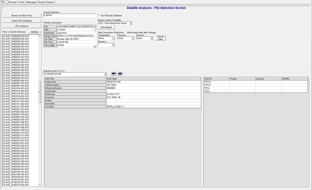
The Data Analysis screen shows the list of data files for the cure cycles. If you click on the file, the system will load the data file and immediately show the run date, run time, recipe, and part information. You can also select and view pre-run integrity check reports such as the Field Check, Sensor Check, Header Check, Drawdown Check, and Leak Check.
Once the file is loaded, you can click on the other tabs to access data-analysis viewing screens.
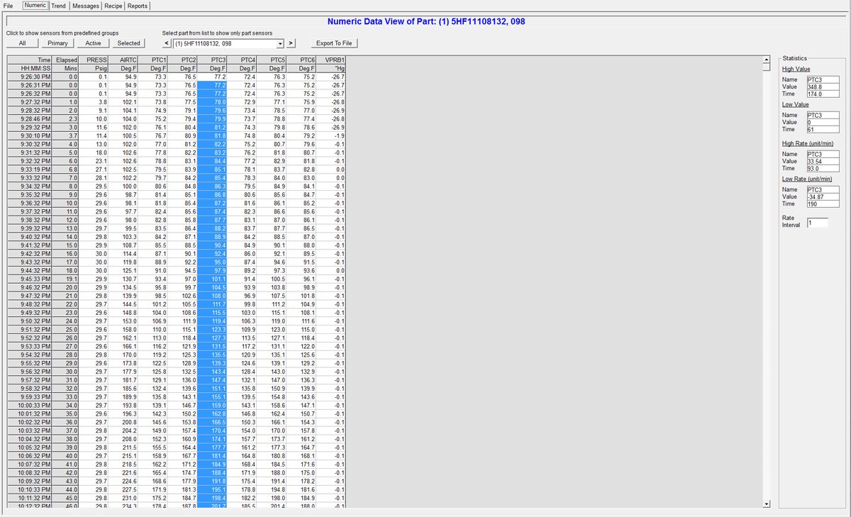
Numeric Viewing Screen - This screen is used to analyze numeric data from the run. You can select active sensors, primary sensors, and sensors on a specific part. You can also select specific sensors to view. If you highlight a certain cell range, the system will display statistics on the data set.
Export Data - Click the Export To File button in order to export the current numeric grid to a comma-delimited text file. This file will be formatted for easy import into Excel.
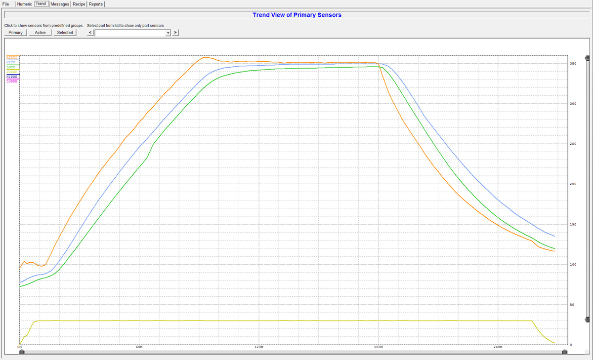
Trend Viewing Screen - This screen is used to display the data in trend form. You can select active sensors, primary sensors, sensors on a specific part, or make a custom selection of certain sensor values. The screen also lets you save specific selection groups for future analysis. The trend display can be zoomed and panned to any specific portion of the run. You can also click and drag the mouse on specific trend lines to identify the rate and value of each data point.
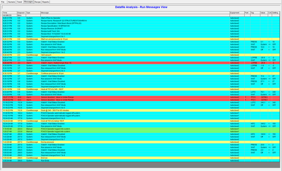
Alarm Viewing Screen - This screen shows all run messages that were created during the run. Blue messages are normal system messages. Green messages are manual interventions. Red messages are alarms.
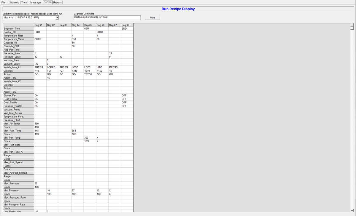
Recipe Viewing Screen - This screen shows the actual recipe used for the run. It will also show revisions of the recipe if the recipe is changed during the turn (security enabled).
HARD-COPY REPORTS - The system includes a number of hard-copy reporting options. They include a numeric report of all parts, individual parts, or only the primary sensors. You can also print color trend reports of all parts, individual parts, and primary sensors. A batch report shows all part information and leak-test results. A messages report shows all alarm messages. Finally, there are three types of quality-analysis reports - batch, part, and exceptions.
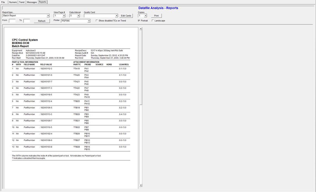
Batch Report- This report shows all parts and all parts information. It also shows the attached thermocouples, vacuum sources, and vacuum probes as well as results of the pre-run leak check.
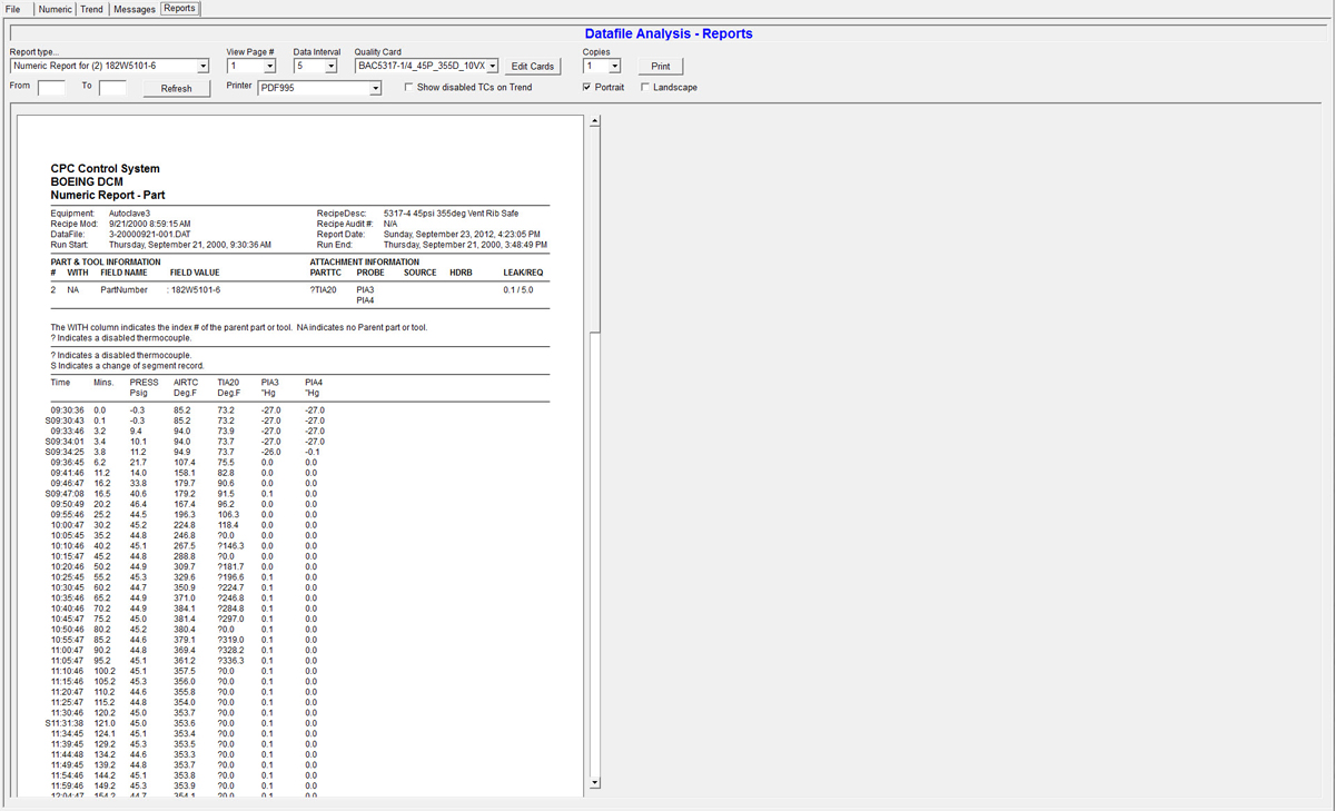
Numeric Report- This report shows numeric interval data. You can choose to print Numeric All Sensors, Numeric Individual Part, or Numeric Primary Sensors
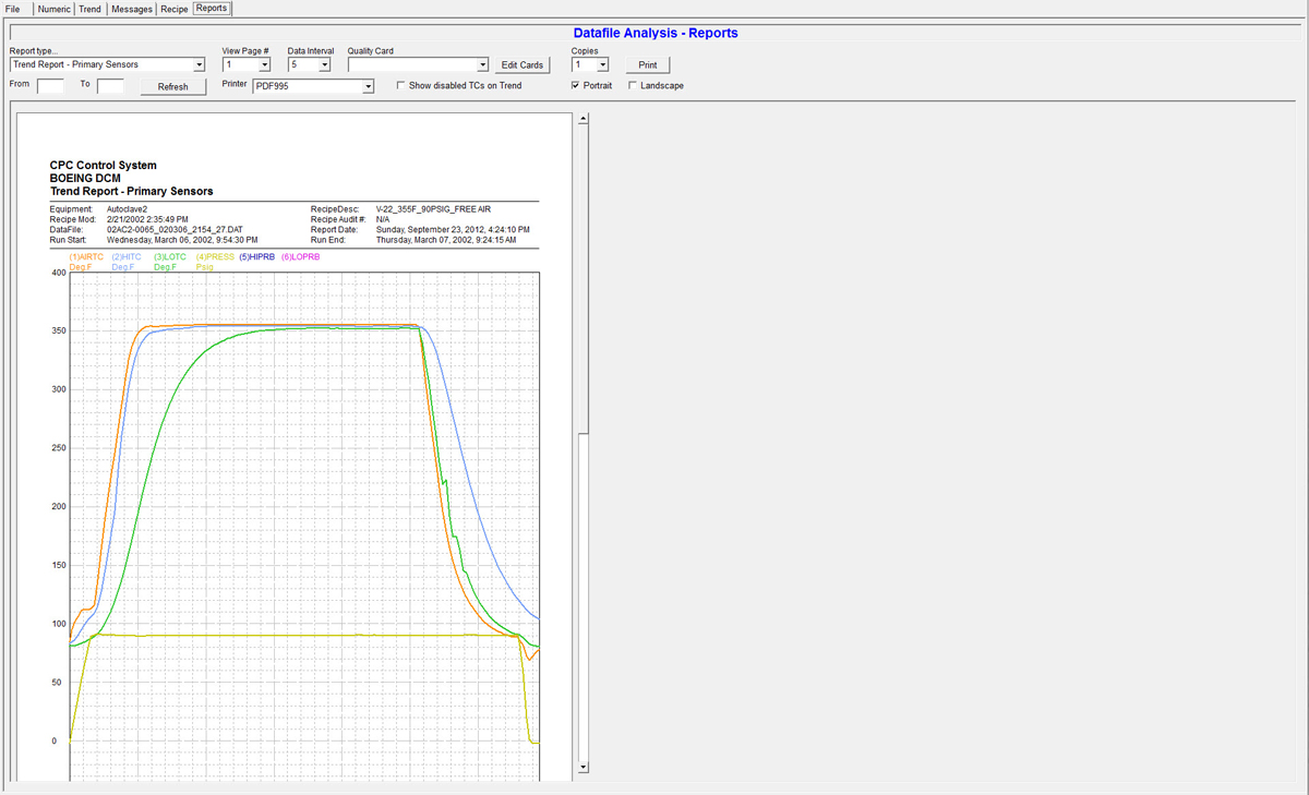
Trend Report - this report shows the trend representation of the data. You can select Trend All Parts, Trend Individual Part, or Trend Primary Sensors
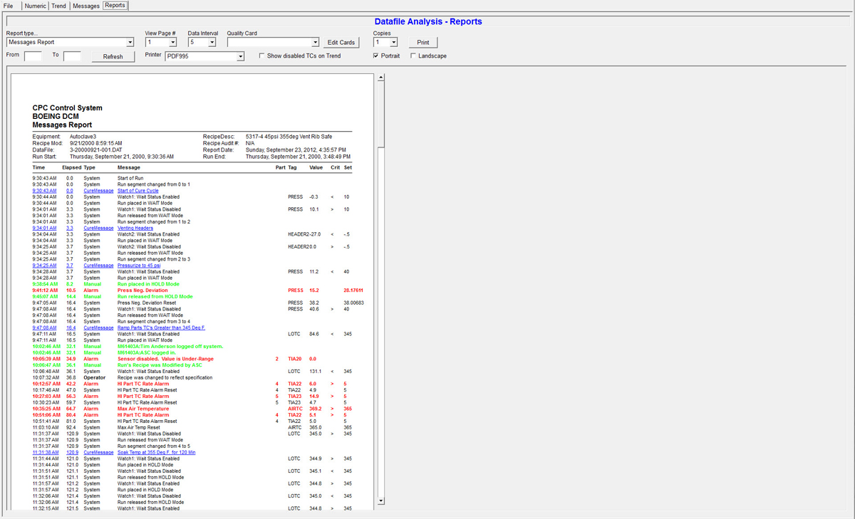
Message Report - this report shows the trend representation of the data. You can select Trend All Parts, Trend Individual Part, or Trend Primary Sensors
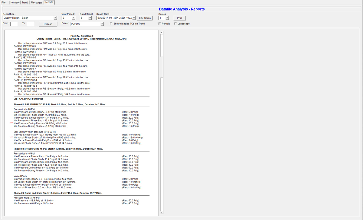
Quality Report - this report shows the results of the quality card analysis. The report can be a Quality Batch or a per-part quality analysis. You can also print an Exceptions Report which shows only the PASS and FAIL of each part with a condensed view of exceptions.
Automatic Quality Inspection
CPC has an integral quality inspection system that automatically analyzes post-run data and verifies whether the data adheres to customer process specifications. The system utilizes pre-programmed "quality cards" which identify temperature, pressure, vacuum, and time tolerances for each phase of the cure cycle.
Why use CPC's Quality Analysis? - A typical cure cycle creates thousands of data points that must adhere to concrete specification tolerances and requirements. Normally the job of validating data falls to a quality inspector who must painstakingly churn through this numeric data. This process is not only time-consuming but can also be subject to human error due to a large amount of data that has to be analyzed. CPC's quality analysis system eliminates the need for human-inspection of this data and provides a comprehensive and exacting analysis of all run data.
The Power of Quality Cards - A quality card is created within CPC by the customer's quality inspection representative. The card provides a step-by-step procedure for data inspection and analysis of the data and is designed to inspect data the same way an inspector would. A card can be matched to a specific recipe, part, or processing spec.
Each card is divided into different phases of inspection. Each phase provides a different set of inspection criteria for each portion of the cure (ie. heating, soak, cooling, etc.) The inspection actions and tolerances are defined in each phase and instruct the system on how to inspect air temperature, part temperature, part temperature rates, pressure, pressure rate, part vacuum, and soak times.
Quality Analysis Manual - Feel free to view our "Quality Analysis System Manual" in our Support screen for a detailed description of the quality analysis system.
Calibration and Certification
Calibration Operations
CPC has advanced calibration tools that are used by customer metrology and calibration personnel to calibrate CPC's sensors, including thermocouples, RTDs, transducers, and transmitters. The calibration function is step-by-step and utilizes real-world calibration value entry to provide linear calibration and multi-point non-linear calibration of sensors. All calibration data can be printed to a report to support Aeroapce NADCAP reporting and traceability requirements.
Certification
Once the system sensors are calibrated, the calibration technician can utilize CPC's builtin certification system to check and record sensor readings at different pre-defined levels. This certification system provides tolerance checking and validation of all calibrations. This certification process results in a concise report showing every sensor and the results of the certifications. Certification reports can also be saved to the PC hard-drive and/or network server.
System Redundancy
Dual-PC Control
CPC's control system and software are designed to take full advantage of a redundant PC architecture. In a Level II redundancy system, two PCs are used to provide primary and backup control of the process. In this configuration, PC-A is the primary controller and PC-B is the backup controller, however, PC-B is also a full-time client station that can be used for viewing and programming during PC-A operations. In the highly unlikely event of a problem with PC-A, PC-B picks up control seamlessly and without operator intervention.
During PC-A operations, all data and configurations are automatically backed-up and stored to PC-B. In this way, when PC-B takes over control, it has a duplicate configuration and data record to continue. The result of this type of redundancy is that even if PC-A never fails, there is a backup data record for every run maintained on the PC-B computer.
PLC Redundancy
For customers who want even greater redundancy, ASC can offer a number of hardware-redundancy options. One option provides a redundant processor for the PLC and redundant communication links to each PLC rack. This requires specific PLC hardware and typically results in a price increase to the control system. For smaller autoclaves and ovens, we might choose to provide a duplicate PLC rack and processor which can be automatically switched into operation when there is a PLC hardware failure. Feel free to discuss your exact redundancy requirements with ASC.
Manual Setpoint Controllers and Chart Recorders
With the power of dual-PC redundancy, ASC typically does not recommend standalone setpoint controllers and chart recorders to our customers. These devices are simplistic and still require interface with the main PLC. They also don't provide even the simplest form of advanced control capability that a PC could provide for autoclave and oven curing. They also require additional maintenance and calibration costs throughout the year. For these reasons, we generally recommend a Level II dual-PC system for redundancy instead of setpoint controllers and recorders.
Note: If a customer is determined to have setpoint controllers and paper data recorders on a CPC system, then we will quote this configuration as an option.
Remote Operations and Viewing
Client/Server Architecture
CPC is a client/server application. CPC-Server is the software that provides all control and data-acquisition of the equipment and process. CPC-Client is the software that provides the HMI (human-machine interface), programming, reporting, and all other operator functions. As a client/server configuration, CPC can have multiple clients connected at any one time. This provides an easy way of having multiple screens at the equipment, remote viewing, and remote control. When you purchase a remote CPC-Client license, you can view and/or control any CPC system from anywhere in your facility - even from your desk. This remote client is virtually identical to the client application installed on the equipment's PCs, so all of the standard security provisions apply.
Customers install remote clients for employees in control rooms, maintenance departments, and quality departments. They are also often installed for viewing from layup areas and clean rooms.
Email and SMS Texting
Email Capability
CPC includes an optional email capability that allows the system to send email messages to multiple parties. The messages can be custom configured to meet your exact data monitoring needs. These messages can include real-time process data, alarm information, and overall equipment and run status.
This advanced email capability also supports bi-directional communication, allowing the system to read incoming emails and respond to written requests. For example, if the incoming email has the text "ALARMS?" in the Subject, the system will respond with the current alarm status. This bi-directional capability is configurable using CPC's powerful scripting language.
Note: CPC's email module requires an outgoing SMTP mail server and an incoming POP3 mail server. If your email system does not support this interface, ASC can provide email services through our servers (ie. [email protected])
SMS Capability
CPC includes an optional SMS capability that allows the system to send SMS text messages to configured destination phone numbers. The option includes GSM modem hardware which must be loaded with an ASC-provided or customer-provided SIM card from a cellular carrier (ie. Verizon, AT&T, etc.)
You can configure the system to send alerts, alarm notifications, run status, and real-time process information at specific times during a run or on an interval basis.
The SMS capability also includes bi-directional capability which allows you to remotely test the equipment from your cell phone and ask for specific updates (ie. ALARMS? or STATUS? or PROCESS?). The system can also be configured to allow remote control commands (ie. END RUN), but those are typically password-protected operations.
MRP & MES Interface
CPC can be configured to communicate to a wide variety of MES (manufacturing execution system) and MRP (manufacturing resource planning) systems. Many companies connect CPC to their internal database systems for bi-directional transfer of run data, part data, and in-process real-time data.
Database Operations - CPC has builtin objects that provide post-run parsing of data to customer SQL, Oracle, or ODBC-enabled databases. These objects also support real-time transfer of process data and a unique feature that imports customer load and part information directly into CPC for the next run. This practically eliminates operator part entry before a run.
Object-Oriented Flexibility - CPC's powerful object-oriented configuration, internal scripting language, and custom screen design capability gives ASC's engineers and customer programmers the tools required to create any interface capability.
Material Modeling
Material Modeling
 AUSTRIA
 BRAZIL
 CHINA
CHINA FRANCE
 GERMANY
 ITALY
ITALY JAPAN
JAPAN LATIN AMERICA
 RUSSIA
 SOUTH KOREA
 SPAIN
SPAIN UK
UK USA
USA