-
The Econoclave Systems
The world’s most popular autoclave, designed to meet the stringent requirements of the aerospace, composites, ballistics, glass, and nuclear industries.
Learn More -
Autoclave Service & Maintenance
ASC’s dedicated service staff can provide yearly preventative maintenance, calibration, troubleshooting, and repairs of existing autoclave other thermal process equipment.
Learn More -
Autoclaved Aerated Concrete
Autoclaved aerated concrete (AAC) is a highly thermally insulated concrete-based material used for both internal and external construction.
Learn More -
Nuclear Transfer & Sampling
The nuclear fuels industry uses autoclaves to prevent the accidental emission of gaseous UF6 (uranium hexafluoride) during feeding, delivery, and sampling operations.
Learn More -
Glass Laminating Autoclaves
ASC's Econoclave GLS models and CPC control systems are used by the glass industry to bond and cure laminated glass for architectural, automotive, and ballistic applications.
Learn More -
Ballistic Armor Autoclave Systems
Ballistic armor is fabricated from a mix of composite materials, steel, silica, and ceramics. In order to increase the quality of the final product, most armor must be bonded and cured in composite curing autoclaves.
SEARCH SITE
Custom Autoclaves
While our standard Econoclave® models represent the best overall value for your thermal and pressure processing requirement, we also have no problem creating a unique product to meet your exact needs.
Econoclave ® designed to meet your requirement
ASC has designed and built hundreds of Econoclaves® for buyers looking for an exact fit to their part load requirements, pressure requirements, temperature requirements, and performance criteria. If you can't find a standard model that fits your size requirement, please fill out our Custom Autoclave Request Form (see tab above) and a sales engineers will contact you to discuss your requirements.
When the Econoclave ® might not be the best choice
The Econoclave ® design is usually the best choice for the composite autoclave buyer because it offers great performance and great value. With the Econoclave ® design, you are assured of getting the most capable autoclave in the world: high quality, high performance, low energy & nitrogen usage, and reduced cost of ownership now and in the future.
Nevertheless, there are a couple of circumstances when the Econoclave ® concept is not the best solution, and in these cases ASC will design and build a conventional annular-air-duct autoclave to satisfy the buyer's needs. When is the Econoclave not the best choice?:
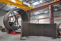
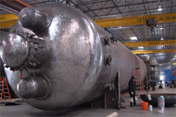
1.) When a customer is curing or processing a large-diameter ( > 10 ft. or 3m) cylindrical part, the design of the autoclave might require that the floor be completely eliminated (rail loading only) so that the part is able to fit. In this case, ASC would normally suggest a conventional annular-ducted autoclave. The reason for this is that the Econoclave ® utilizes the under-floor area (or side area in GLS Econoclaves) to fit the cooling radiator and heater. If the floor is eliminated, then there is no room for these items and they will have to be placed at the rear of the autoclave (conventional). This will increase the overall width (air-duct) and length (heater, cooling, and transition) of the pressure vessel and will result in an increase in price and overall operation costs in the future. Note: In cases where the part diameter is not very large, ASC will still recommend an Econoclave design. We would merely increase the diameter of the equipment slightly to accommodate the part. This choice still represents an overall better value than a conventional autoclave.
2.) In cases where the overall part and tooling load is large and the required heating and cooling rates are high and the autoclave length is limited, ASC might not be able to fit the necessary heaters and cooling radiators below the floor. In this specific case ASC will probably suggest a conventional autoclave design.
Please click on the "Request Form" tab above to configure a custom autoclave to meet your needs.
ST- Startup and training by an ASC field engineer
This option provides all costs for an ASC field engineer to travel to your facility to perform startup of the equipment/control system and training of your personnel. The option includes all costs of on-site engineering labor, air fare, travel time, rental car, hotel, and subsistence costs.
For small Econoclaves and control systems, the on-site time is typically 5 days. For larger Econoclaves/Autoclaves, startup and training can require 2 weeks or more.
During the startup activity, the engineer will run through and validate all safety and functional systems and perform test runs to validate performance in accordance with your requirement. The engineer will also train your engineers, operators, quality and maintenance personnel in the proper programming, operations, and support of the Econoclave.
Training certificates will be provided upon request.
VS - Vessel design and construction code
Although many countries accept the ASME Division I, Section VIII pressure vessel standard, there are cases where an alternate pressure vessel code will be required. In these cases, there will be additional costs that are required for authorized inspection services.
- VS1 ASME Division I, Section VIII - This is the pressure vessel design code accepted by the United States and hundreds of other countries. This selection will not increase price.
- VS2 Pressure Equipment Directive - This is the code that governs pressure vessels for all EU countries. In this case, ASC will insure that the pressure vessel meets the directive with 3rd-party notified body approval.
- VS3 China Pressure Vessel Code - This is the code that is required for all pressure vessels imported into China.
- VS4 JIS - This is the code that is required for all pressure vessels operating in Japan.
- VS5 Other. Please describe.
If you are unsure about the requirements of your country, please contact an ASC sales engineer and he will assist you in determining the correct code for construction.
VP - Vacuum pumps
While some customers prefer to use in-house vacuum systems to supply vacuum to the Econoclave, most prefer that a dedicated pump or pumps be provided on the Econoclave skid.
- VP1 One vacuum pump, fully integrated to autoclave, with PC controls.
- VP2 Two vacuum pumps, fully integrated to autoclave, with PC auto-switching and redundancy logic/controls.
ASC standardizes on an Airtech L-series, rotary-vane, oil-seal vacuum pump for our aerospace vacuum applications. The Airtech pump includes an exhaust filter, vibration isolators, and anti-suckback valve. The pump achieves a vacuum level of 29.8 "Hg (2 mmhg) at 60hz operation and sea-level.
For the VP2 option, ASC will provide two (2) pumps with PC-control logic that allows manual selection of a single pump, dual pump operation, auto-switching for balance duty and redundancy.
Pump Ratings
For composite applications, ASC has developed a simple rule of thumb for sizing vacuum pumps. We generally offer a pump that delivers a capacity that will provide approximately 2 cfm to each of the autoclave’s source lines. For example, a 10 source line application, we would select an L25 pump, which delivers 20 cfm.
| Series | cfm (60hz) | m3/hr (50hz) | HP | KW |
| L12 | 7 | 6.6 | .75 | .5 |
| L21 | 15 | 14.1 | 1 | .75 |
| L25 | 21 | 19.8 | 1.5 | 1.1 |
| L40 | 31 | 29.2 | 2 | 1.5 |
| L63 | 45 | 42.4 | 3 | 2.25 |
| L100 | 70 | 66 | 5 | 3.75 |
| L160C | 117 | 110 | 7.5 | 5.6 |
| L230B | 155 | 146 | 7.5 | 5.6 |
| L250D | 180 | 169 | 10 | 7.5 |
| L400C | 330 | 311 | 15 | 11 |
| L630C | 460 | 434 | 25 | 18.7 |
PW - Power, voltage, frequency selection
Although the standard Econoclave autoclave is designed for 480 volt / 3phase service and 120 volt control power, we can design it to accommodate any international voltage and frequency requirement.
Please select one of the options below, or if your specific power requirement is not shown, select PW6 and explain your exact power requirements.
- PW1 480 volt / 3 phase / 60hz primary power and 120vac control power.
- PW2 380 volt / 3 phase / 50hz primary power and 24vdc control power.
- PW3 400 volt / 3 phase / 50hz primary power and 24vdc control power.
- PW4 415 volt / 3 phase / 50hz primary power and 24vdc control power.
- PW5 575 volt / 3 phase / 60hz primary power and 24vdc control power.
- PW6 Custom power - please describe.
If you are unsure about your exact requirements, please see the following document for international voltage and frequencies. Note: ASC's manufacturing plant is in the US and therefore utilizes 480V/3PH power. For this reason, when PW2-PW6 is selected, ASC will be required utilize rental diesel generator power to test the autoclave during in-house tests. This generator rental cost as well as a slight increase in motor costs will be priced into the project, so one should expect a slight increase in autoclave price when PW2-PW6 is selected.
CL - Cooling system options
The autoclave utilizes water for auxiliary cooling requirements (ie. fan motor capsule) and for main cooling requirements. Some customers prefer to utilize their own water delivery system, however the majority of Econoclave buyers prefer that ASC provide an integrated cooling system for the equipment.
- CL1 Cooling system with open evaporative tower
- CL1S Cooling system with open evaporative tower and stand
- CL1T Cooling system with open evaporative tower and TDS flushing system
- CL1ST Cooling system with open evaporative tower, stand, and TDS flushing system
- CL2 Cooling system with closed evaporative tower
- CL3 Cooling system with water-water exchanger
- CL4 Cooling system with radiator fan exchanger
- CL5 Cooling system with refrigerated chiller
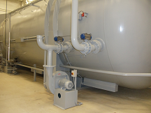
Basic theory of Operation
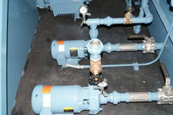
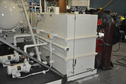
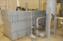
The typical Econoclave water system has a water holding tank, main circulation pump, tower circulation pump, and a cooling tower. The main circulation pump transfers cold water from the tank to the Econoclave for fan capsule cooling requirements and main cooling requirements and then back to the tank. As the temperature in the water tank increases, the control system will turn on the tower circulation pump and tower fan. The tower pump will transfer warm water from the tank to the tower and then back to the tank.
The tower serves to strip the heat from the water, thus delivering cold water back to the tank. Note that ASC's towers are drained completely back to the tank after the autoclave cycle is complete. The tower and tower pump is sized to maintain the water temperature below 120 °F (48 °C), even during maximum autoclave cooling at full load.
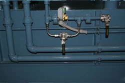
Each pump includes flexible stainless hose isolator, maintenance isolation valves, pressure gauge, and local disconnect switch.
Water Tank
The water tank is an ASC-designed tank constructed of heavy-duty, 304 stainless-steel sheet metal. The tank volume is calculated based on size of autoclave and cooling capacity.
The tank is equipped with a level control valve and level controller. For larger autoclaves the tank also is equipped with high and low alarm indication.
Fully integrated and tested
With the exception of very large Econoclaves, all CL options come fully integrated and tested on the autoclave in our shop. The cooling tank, pumps, and controls are mounted on the rear skid, plumbed, and electrically connected. The tower is always shipped separately for installation by customer on their roof or on separate and optional tower stand.
Selecting an open tower, closed tower, exchanger, or chiller.
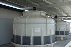
Most mid-size to large-size Econoclaves are sold with cooling systems that incorporate an open evaporative tower. The open evaporative tower strips the heat from the water by running the water down a PVC membrane while simultaneously directing forced air across the water. This action evaporates some of the water and removes the heat from the remaining portion. In this configuration, the water level will slowly drop during a tower cycle due to evaporation, and the level control system will "makeup" this water. (options CL1S and CL1ST)
While the open style of tower is inexpensive and popular, it is not always the best choice, especially in cases where the customer wants to utilize glycol in the water for freeze protection or in cases where the customer wants a "closed" system. In this case, a closed tower (CL2), radiator-style exchanger (CL4), or water-water exchanger (CL3) is provided.
In the closed tower configuration (CL2), autoclave process water flows through a stainless-steel tube bundle in the tower. The evaporation occurs with a secondary water loop which is managed by the tower. A small pump delivers water from the tower basin, to the top of the tube bundle, at which time it gravity drains/drips back to the basin.
The radiator-style exchanger configuration (CL2) utilizes a radiator tube/fin exchanger forced air fan delivery. As a non-evaporative solution, the autoclave water will only be able to cool to the dry-bulb ambient temperature. This is a good candidate for cold-weather areas where glycol will be utilized for cooling.
The water-water exchanger configuration (CL3) utilizes a liquid-media plate exchanger. In this configuration, a cooling system pump delivers warm tank water to the exchanger and then back to the tank. On the other side of the heat exchanger, the customer brings process or chilled water to the exchanger and then back to their own cooling system. This type of system is often selected for small Econoclaves (ie. EC1x2, 2x4, 3x5), or in cases where the customer has ample process water available.
Due to the large amount of cooling capacity required for the Econoclave, the refrigeration chiller configuration (CL4) is an extremely expensive way to cool the autoclave. For this reason, we only suggest a customer purchase option CL4 for a small autoclave that can’t use one of the other configurations, or for an autoclave that must achieve a very low final temperature and/or rapid low-temperature cooling rate.
The benefits of evaporation (CL1 and CL2)
Whether you are using an open or closed evaporative tower, there are big benefits to using the evaporative configuration instead of the radiator-style exchanger configuration. Evaporative towers are able to cool the autoclave below the current ambient temperature, and thus provide much better low-temperature cooling in the autoclave. In most cases, the water can be cooled to near the wet-bulb temperature, which will always be much lower then ambient (dry-bulb) temperature. For example, in a dry climate, the wet-bulb temperature might be 72 °F (22 °C) while the ambient temperature is 95 °F (35 °C).
Handling total dissolved solids (CL1T and CL1ST)
With the evaporative configuration, you should expect that the dissolved solids in the water will slowly increase. Over time, the solids concentration can increase to a level that will cause lime and scale buildup on the inside of the autoclave cooling heat-exchanger. For this reason, regular maintenance of the water tank should include flushing the tank and refilling with fresh water. For larger Econoclaves that use an open evaporative tower, ASC suggests selecting the TDS option, which provides a conductivity sensor and automated flushing system to control the TDS (total dissolved solids) in the water tank.
Tower stand (CL1S and CL1ST)
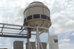
For open tower configuration, the bottom of the tower must be elevated at least 4-6 ft. above the water level in the tank. For this reason, the tower can be mounted on the roof of the building or can be mounted on an elevated stand structure. If you prefer to mount the tower near the autoclave and not on the roof, please select either the CL1S or CL2S option above.
VR - Controlled vacuum receiver system
Many composite applications require full vacuum during and or at the beginning of the cure cycle. In these cases, there is little need to control the level of the vacuum to the parts. However, for high-temperature polyimids and honeycomb reinforced parts, there is often the need to provide partial vacuum (ie. -10"Hg) to the parts. In these cases you will need to have a controlled vacuum receiver.
The VR option provides an integrated receiver tank, transducer connected to PC system, and two PC-controlled valves. Once configured, the system will provide Recipe-based programming and control of the system vacuum to +/- 1" hg (24 mm Hg) accuracy. The VR option includes solenoid operating valves for Econoclaves with minimal vacuum source ports, and proportional valves for larger Econoclave systems.
VT - VacTrap ™ chilled resin traps
For composite curing applications with high volatile content (ie. high-temperature polyimides), we recommend chilled VacTrap ™ assemblies instead of the conventional ambient temperature filter traps. The VacTrap will be much more effective condensing volatiles and solvents during high-temperature curing operations.
The VacTrap is an ASC designed modular vacuum system that utilizes conventional stainless-steel ball valves, a proprietary custom aluminum trap blocks, and a chiller.
TR - Transportation of Econoclave to your facility
Although many customers arrange and procure their own transportation, ASC can quote transportation of your Econoclave from ASC’s plant to your facility.
ASC will utilize one of our preferred shippers to deliver the Econoclave to your facility. The transportation option includes all costs, including insurance and ASC’s markup. For cases of ocean transportation, ASC can quote CIF Port of entry or DDU to your factory.
Note: ASC will utilize our standard markup for transportation costs, so it will always be more cost-effective for you to purchase transportation directly from a carrier rather than from ASC provide this.
RG - Offload and Rigging of the Econoclave at your facility
Many customers prefer to handle rigging with their preferred local contractors, however on turnkey projects and on larger Econoclave deliveries, customers often select the ASC rigging option in order to provide a sole-source responsibility for the effort.
The RIG option provides all costs to offload the autoclave from the truck at your facility and rig the autoclave into its final resting place in your plant. ASC will typically utilize our own personnel as well as local crane and rigging personnel as required.
For larger autoclave, this option also includes leveling of the autoclave in the pit prior to installation.
IN - Installation of the Econoclave at your facility
While Econoclaves are easy to install, most customers still prefer that ASC install the autoclave at their facility. There are a couple of installation options that you might want to consider.
- IN1 ASC provides an installation expert to supervise customer’s employees and/or contractor installation.
- IN2 ASC is responsible for installing the autoclave and auxiliary systems (see description below)
IN1 –Supervision by ASC field installation expert
This option is less expensive than the full installation as it provides a single expert to supervise the installation effort by the customer’s employees and/or locally procured mechanical and electrical contractors.
The installation effort can require as little as 3-5 days on small Econoclaves up to 5-6 weeks for large and complex units.
The option includes:
- ASC field installation expert for a fixed number of days on-site at your facility.
- Round-trip air-fare
- Rental vehicle, hotel, and subsistence for the duration of the stay.
IN2 –Installation of autoclave at customer facility
This option provides all material and labor required to install the autoclave at your facility:
Includes: (If you want ASC to take on additional tasks, please contact an ASC sales engineer for a custom installation package)
- Mechanical and electrical between the following:
- Autoclave to water tank
- Main and auxiliary water supply/return piping
- Conduit, wire, and connections
- Autoclave to compressed air utilities (see assumptions)
- Piping and supports as required
- Autoclave to pressurized nitrogen utilities
- Piping and supports as required
- Water tank to plant water utilities
- Piping and supports as required
- Vacuum vent from pump and vent manifold to building vent or building exterior
- Piping and supports as required
- Autoclave silencer to customer’s roof and/or wall penetration.
- Piping and supports, assuming
- Expansion-anchor lagging of autoclave to concrete floor.
- For pit mounted autoclaves with BR (bridge) option:
- Bridge placement, lagging, and concrete fill if required.
- Air-over-oil tank placement
- Piping
- Conduit, wire, and connections.
- Floor-mounted control enclosure
- Placement
- Conduit and wire
- Autoclave to water tank
- Mechanical labor to install the autoclave, air-fare, travel time, hotel and subsistence costs.
- Electrical labor to install the autoclave, air-fare, travel time, hotel and subsistence costs.
- All material except where identified in the Excludes section.
- Rental vehicle(s) and lift equipment as required.
Assumptions: (The standard IN2 option is based on the following assumptions. If you prefer ASC to take on some of these items, please call ASC for a custom installation package.) Water, compressed air, and pressurized nitrogen utilizes are within 10 ft. of autoclave.
- Electrical service disconnect is terminated within 10 ft. of autoclave or customer lands electrical conductors into ASC’s power enclosure.
- If cooling tower is placed on the customer’s roof, ASC assumes that customer will have placed this tower prior to ASC’s arrival.
- Cooling tower is within 30 ft (pipe length) of water tank.
- Exhaust piping will not exceed 30 ft. (pipe length)
- Vacuum vent pipe is no longer than 30 ft. from autoclave
- Customer provides 480V power to job-site for welding and other electrical work.
- Customer provides waste bin and removal, unless specifically included.
Exclusions: (The standard IN2 option has the following exclusions, which might be offered optionally. If you prefer ASC to take on some of these items, please call ASC for a custom installation package.)
- Transportation of autoclave to customer site (see TR option)
- Rigging of autoclave into pit and/or final location (see RG option)
- Any and all civil work, including foundations, saddle grouting, walls, wall penetrations, roof penetrations, and roof sealing.
- Pit ladders, railings, pit sump pump, and pit amendments.
- Startup and training (see ST option)
- Tower rigging and crane-assisted placement on roof (see Assumptions)
PG - Purge system with oxygen monitoring
Most composite autoclaves utilize nitrogen as the pressurization media. After a cure cycle, there is a need to purge the nitrogen from the autoclave and bring in fresh breathable air prior to allowing personnel to enter the autoclave.
In the past many companies have purged this unsafe atmosphere by putting in place a procedure that required the operators to open the door and run the internal autoclave circulation fan for 5-10 minutes prior to entering. While this method does adequately purge the nitrogen from the autoclave and replace it with breathable air, it is not an automatic function and relies heavily upon the diligence of the operators and supervisors in the production area.
ASC strongly recommends the use of an automated purge system for all walk-in autoclave that utilize nitrogen. The PG - purge system option includes the following:
- One (1) high-pressure purge blower, rated to delivery breathable air to the autoclave (19.5% oxygen) in under 30 minutes.
- One (1) high-capacity purge air inlet valve.
- One (1) high-capacity nitrogen outlet valve
- One (1) Safety blow-out box
- Air sampling pump and air sampling valve(s) positioned to sample autoclave air.
- Oxygen monitoring instrument
- Door interlock to disable door open operation until 19.5% oxygen is monitored at instrument.
Multi-point sampling
For small and mid-size autoclave, the sampling system utilizes a single connection at the rear of the autoclave, however for longer autoclaves, ASC incorporates multiple sampling valves that will sequence and repeat to insure safe oxygen levels at different points down the length of the autoclave.
Air sampling and monitoring
The integrated oxygen monitoring system automatically samples the autoclave at the end of a cure cycle and confirms safe oxygen levels prior to allowing autoclave door operation.
The monitoring instrument, manufactured by AMI Devices, has a 10-year sensor and displays the oxygen percentage for the operator to view. The monitor is also connected to a stack-light which illuminates Red when it is unsafe to enter and Green when the purge cycle has reached a minimum purge time AND the oxygen level has been verified to be at least 19.5%.
In order to provide an even safer system, ASC incorporated a flow monitoring sensor to guarantee that the sample pump is operating properly during the monitoring period. ASC is the only company to have this feature.
Additionally, the sampling logic is designed to require that the autoclave fan is running during a purge sequence. If the fan is stopped prematurely, the purge cycle will fail.
Purge completion time
Although there is no specific industry standard, most purge systems are designed to achieve safe breathable air in less than 30 minutes. If you require a shorter purge sequence, please contact ASC sales engineer to discuss other custom options. Note that reduction in purge time can cause the price to increase dramatically.
Back-pressure blower safety
Although a purge system is a recommended safety system for the autoclave, an incorrectly designed purge system can cause catastrophic failure and injury if the purge air valve were to open while the autoclave is fully pressurized. This has happened a few times in the last decade on autoclaves built by some of our competitors, and the result has been a catastrophic failure of the purge blower and explosive shrapnel.
In order to mitigate the risk of blower back-pressure, ASC’s purge system incorporates a series of a safety features that include a hard-wired pressure interlock for the fresh air valve, a single-acting actuator for the valve, and a proprietary blow-out box which will relieve and vent excess-pressure in the unlikely event that the valve opens.
BG - Pit transfer bridge
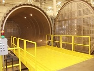
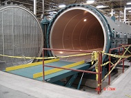
For large autoclaves that are mounted in pits, you will need to purchase a bridge system which spans from the shop floor to the autoclave (see photo above).
ASC can design and manufacture a number of different styles of bridge systems.
- BG1 – Rotating bridge with air-over-hydraulic lift cylinder, manual rotation
- BG1A – Rotating bridge with air-over-hydraulic lift cylinder, automated rotation
- BG2 – Sliding bridge, manual slide
- BG2A – Sliding bridge, automated slide
- BG3 – Pivoting draw-bridge.
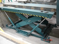
- BG4 - Scissor-lift bridge
BG1 and BG1A – Rotating Bridge
Due to its simplicity and low cost, BG1 rotating bridge is the most popular bridge configuration.
In this configuration, the bridge moves up and down using an automotive-style air-over-hydraulic cylinder which is mounted into the pit floor. During a cure cycle the bridge is stored at the pit floor level in the 90-degree position. When the door opens, the bridge is raised to the UP position, manually rotated to a 0 degree position, and lowered into the final Load position. Unlike scissor lift configuration, the cylinder is only for movement and is not utilized during part and tool loading operations. In the “Load” position, the bridge is actually positioned and resting in a recessed slot in pit wall (shop floor side) and on a physical landing at the autoclave. This passive support is extremely safe.
On larger bridges ASC recommends a BG1A option, which provides a dual-cylinder and a automatic hydraulically-operated rotation assembly.
BG2 / BG2A – Sliding bridge
The sliding bridge is a simple system where the bridge platform is mounted on a cart that can roll out of the way. This type of bridge is only selected by customers who have spare space next to the autoclave and don’t mind a slightly larger pit. The standard BG2 bridge is mean to be manually pulled and pushed into place.
The BG2A provides a long air cylinder that positions the platform in the Load and Store positions.
BG3 – Pivoting draw bridge
The pivoting draw-bridge utilizes a large hydraulic cylinder to pivot the bridge from its Load position to a vertical Store position. In the configuration, during the cure cycle the bridge is positioned vertically in front of the autoclave door.
BG4 – Scissor-lift bridge
The configuration utilizes a conventional hydraulic scissor-lift to raise and lower the bridge. In this configuration, the pit must be much deeper to accommodate the scissor mechanism. Also, in the configuration, the scissor hydraulics are used to lift the bridge and also to maintain the bridge and part/tool load during loading operations. For this reason, scissor bridges are provided with corner-positioned lock pins which are used to insure that the bridge stability during loading.
CT - Floor and autoclave carts
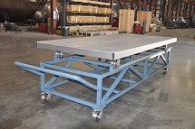
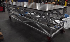
ASC manufactures a wide variety of carts for autoclaves and oven applications.
- CTT – Transfer cart, used to transfer autoclave cart to autoclave, non-pit-mounted autoclaves
- CTA1 - Autoclave cart, single-level, standard top
- CTA2 - Autoclave cart, multi-level, standard top
- CTAX – Custom cart.
CTT – Transfer Cart
The transfer cart is used on the shop floor to transfer the autoclave cart to and from the layup room. The cart has a handle, one pair of swivel wheels, and a lock mechanism that is used to secure the transfer cart to the autoclave during movement of the autoclave cart into and out of the autoclave.
CTA1 – Single-level autoclave cart
This option provides a single-level autoclave cart that is designed to roll on the autoclave rails (V-groove or channel). The autoclave cart surface can be expanded metal or flat plate. .
CTA2 – Multi-level autoclave cart
This option provides a multi-level autoclave cart, which is designed to stack tools and parts in the autoclave. The ASC sales engineer will contact you to discuss your exact cart requirements.
CTA3 – Custom
If you have a specific requirement, select CTAX and provide a brief description of the cart. Our sales engineer will contact you to discuss.
Custom Autoclave RFQ Form
Copyright © 2026 ASC Process Systems.
 AUSTRIA
 BRAZIL
 CHINA
CHINA FRANCE
 GERMANY
 ITALY
ITALY JAPAN
JAPAN LATIN AMERICA
 RUSSIA
 SOUTH KOREA
 SPAIN
SPAIN UK
UK USA
USA